Prepare engine mount
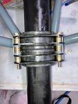
There were a few issues with the engine mount. Some of these were a bit of a false alarm, in the light of subsequent observations. The first thing I ran into was how tightly the bushes grip the nose wheel tube. I was aware that these do have to be sanded, but I also noticed quite a bit of paint build on both the lower and upper bushing supports. I also noticed that these supports had welded a sort of doubler sheet of steel to bring the thickness into agreement with the slots in the bushings. In some cases these doublers were noticeably misaligned with the main support metal. So I did sand the paint back to metal and also smoothed down these misalignments where they were proud of the primary shape, reprimed and repainted. The correction here was on the 0.1-0.2mm level.
Only after this did I realise the primary reason for the very tight hold of the mounts on the nosegear tube. I was puzzled how separately the upper and low bushings did not grip the tube unduly. The reason actually was that these mounts are not collinear, so the tube actually passes between the mounts at an angle, and therefore the tube makes contact only on portions of the bushings. The departure from collinearity is about 5mm over a separation of ~180mm or an angle of about 1.5 degrees!
So the effort in smoothing down the paint build was actually a bit of misdirection. On the other hand, less sanding of the bushes would be required to allow the nosegear tube to slide freely. But also, owing to this, the bearing surfaces between the bushings and the nosegear tube would be a little less, because the bushings are about 0.1-0.2mm further apart compared to what they would have been.
A possible benefit to having to remove less material from the bushing is that there is less chance of the bushings binding if the semi-circular pieces from which they are composed wander rotationally over time in the mounts. But also, on the other hand, the near absence of a significant divot being sanded out of the mount will prevent same from acting to keep the semi-circular bushing halves in they original positions.
I examined another more recent engine mount and found that it did not have this departure from collinearity. I presume that I was not particularly unlucky and that the degree of collinearity was a not-so-well controlled variable in the past, and that many Slings out in the field have the same property. As I have not heard of it being a problem and that I am also not in the habit of doing heavy nosewheel landings I do not expect it to be a problem.
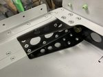
Another issue with my engine mount was a slight warping of one of the layers (there are 4 layers) of the upper bushing mount which prevented one of the AN3-26 bolts from being fully pushed through, that is not without damaging the thread. The misalignment was corrected by opening up the 3/16" hole on the offending layer, by about 0.15mm. Consequently, the hole on this layer is slightly elongated but there are four layers, and I have also ensured the spaces between the layers are tightly packed with washers, so that the bolt can be properly torqued. The clamping force of the bolt is therefore fully established. Such a clamping force also helps to ensure the shear load capability of even the affected layer is still substantially maintained. For good measure I replaced the AN3 bolts on both the upper and lower bushing mounts with AN173 close tolerance equivalents, achieving an even tighter fit. In any case the elongation of the hole in the single layer of the upper bushing mount is in a lateral direction orthogonal to the fore-aft direction of significant shear loading in servce.
Author
This post is from Adam Dickson