Review of fuselage mounted equipment connectivity
There are three boxes mounted on the fuselage bulkhead panel, the radio, flarm-fusion and the transponder
Flarm-fusion
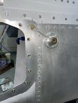
The flarm-fusion connector is a bit awkward to get to in field service being located behind the SMA connectors, so I will associate its harness with the fuselage rather than the panel, routing any lines that need to go to the panel via the midsection interconnect.
So removal of the panel does not require disconnection of anything flarm-fusion specific
The DB9 connections are
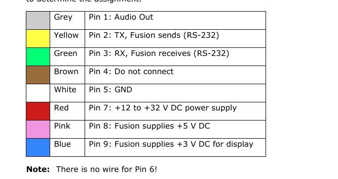
Pin 1 - audio out will connect to the mutable or nonmutable audio input of the intercom. As the intercom interconnect is also fuselage located a direct connection is made.
Pin 2 and 3, Tx and Rx will be routed to one of the Dynon Skyview serial ports so these will go through the midsection interconnect
Pin 5 and 7, Gnd and Pwr will be routed to the panel so will also go through the midsection interconnect. These power lines might be aggregated with other fuselage-mounted boxes before passing through the midsection interconnect .
Decision taken to not aggregate - to provide separate power to flarm with its own breaker. This circuit will also power the trafficview80.
4 wires through midsection interconnect
Transponder
A transponder cable loom was purchased the number of connections is small, so it makes sense for this also to make this loom fuselage-centric
So removal of the panel does not require disconnection of anything transponder specific
The only pins that need to be connected are
pin 5 - orange - serial rx, connects to serial 1 tx of the Skyview so routed through the midsection interconnect
pin 6 - violet - serial tx, connects to serial 1 rx of the Skyview so routed through the midsection interconnect
pin 14 - gnd - routed through the midsection interconnect
pin 15 - pwr - routed through the midsection interconnect
pins 14 and 15 may be aggregated with other fuselage-mounted boxes before passing through the midsection interconnect
As per schematic the pwr and gnd aggregate with ADS-B In
pin 20 - green - ident switch in - since this loom is fuselage-based this wire will be directly to the ident line coming from the stick loom and connected
The following wires will be removed from the supplied cable loom
pin19 - yellow - squat
pin 3 - white - gps serial port
COM Radio
It is an each-way choice whether to have the loom for this unit fuselage-mounted or panel mounted. There are roughly equal numbers of wires that connect to the (fuselage mounted) intercom loom and to the skyview and power busses. I will follow the pattern above, fuselage mounting, largely because of easier panel removal by avoiding the need to unplug the com radio when removing the panel. In this case the following is true
pins 24, 25 power in - routed through the midsection interconnect
pins 19, 22 ground in - routed through the midsection interconnect
pins 24, 25, 19, 22 may be aggregated with other fuselage-mounted boxes before passing through the midsection interconnect
pin 13 - sv-com panel enable routed to enable of com panel via midsection interconnect
pin 5 - data rx routed to data tx of com panel via midsection interconnect
pin 6 - data rx routed to data tx of com panel via midsection interconnect
The remaining lines are then connected directly to the intercom loom
pin1 - phones ground
pin 2 - phones out
pin 23 - mic in
pin 15 - ptt in
pin 9 - mic/ptt gorund
Note that the power circuit powering the COM radio also powers the COM panel
The two each pwr and gnd wires are combined before passing through the midsection interconnect
The pwr and gnd are not aggregated with other fuselage mounted boxes
So 5 wires pass through the midsection interconnect
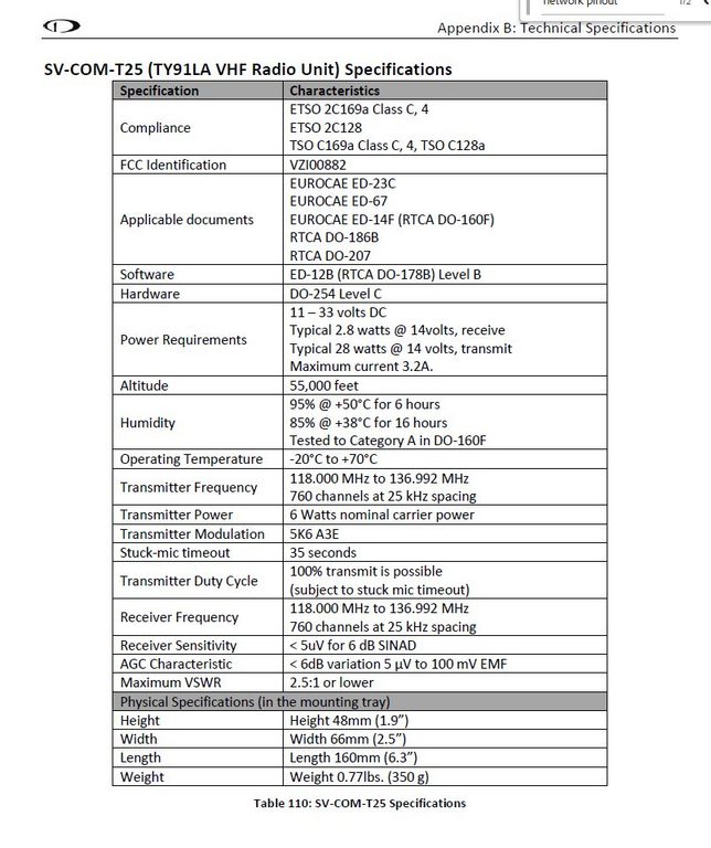
Max current draw 3.2A. Now there are paired 20AWG supplying power. If one of these shorts to ground the fault current will pass though one 20AWG wire. So the circuit breaker should be at most 7.5A. The schematic suggests 5A. I will combine each 20AWG into a 18AWG wire for passing though the midsection interconnect. The wire passing back to the panel will also be 18AWG. Purple-band size 20 connectors will be used.
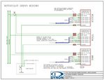
Servos
These - 2 units - are also fuselage mounted.
The power and gnd of the two units are aggregated (check currents) and passing through the midsection interconnect
The disconnect lines are aggregated and connected directly to the stick looms
The 4 network lines could be aggregated and passed though the midsection interconnect, or routed separately to the panel and connected with DB15s. I am leaning towards the former.
Magnetometer
The 4 network lines could pass though the midsection interconnect, or routed separately to the panel and connected with DB15s. I am leaning towards the former as these lines can be aggregated with the servos.
The cable is a skyview network cable
pin 7 - red - power 1
pin 2 - black - ground 1
pin 1 - green - data 1A
pin 6 - blue - data 1B
pin 9 - white/red - power 2
pin 3 - white/black - gnd 2
pin 8 - white/green - data 2A
pin 4 - white/blue - data 2B
pin 5 - orange - EMS auxillary voltage
In the magnetometer, the two grounds are connected, the two powers are not, and the power 2 appears to be unconnected. From forums it is found that the EMS auxillary voltage is unused.
So there is just the 4 network wires, power, and ground.
One option is to route all 9 lines though the midsection interconnect. Since the 4 network lines are already routed to the servos, only 5 additional lines would be need to bring the full dynon network onto the midsection interconnect
The other option is to bring the magnetometer network cable separately to the panel, completely bypassing the interconnect
Aggregation
The dynon schematics suggest aggregating:
- the com panel and com radio power downstream of a single circuit breaker
- the transponder and ADS-B receiver downstream of a single circuit breaker
The com radio power (and ground) will therefore be routed though the midsection interconnect on separate pins
The transponder and ADS-B In (fuselage mounted) power and ground can therefore be aggregated into a single wire pair before passing through the midsection interconnect
I am inclined to place the flarm-fusion and trafficview80 downstream of a single circuit breaker. This means the flarm-fusion power (and ground) will be routed though the midsection interconnect on separate pins
Author
This post is from Adam Dickson