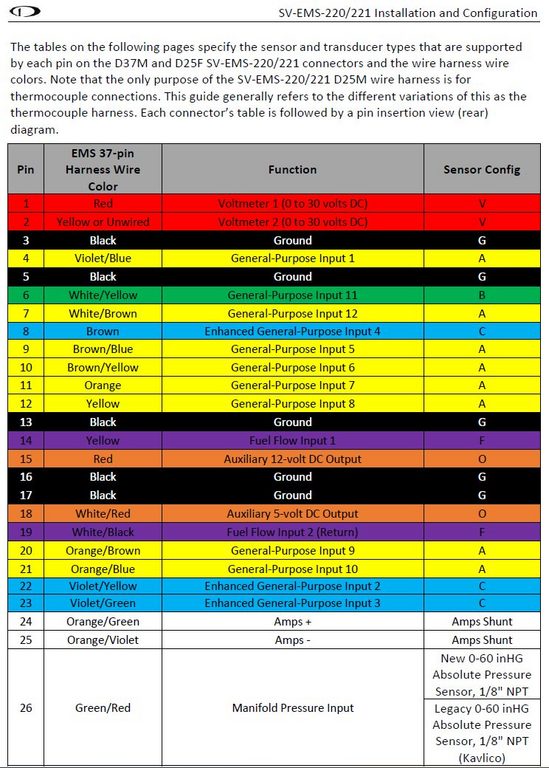
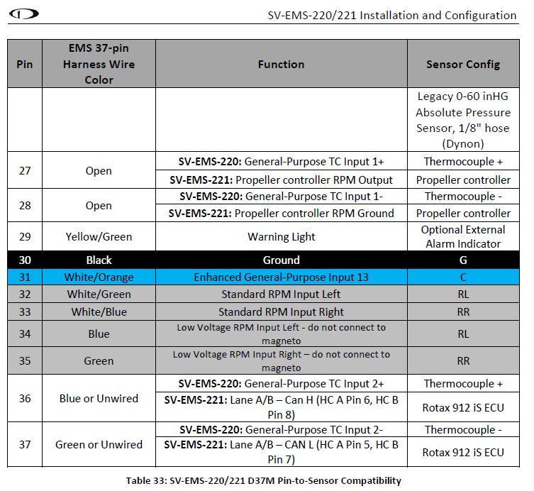
EMS220 pin assignments
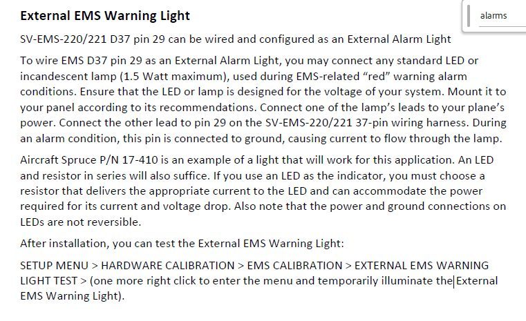
Extract of Skyview Installation Manual, Revision AV, November 2025
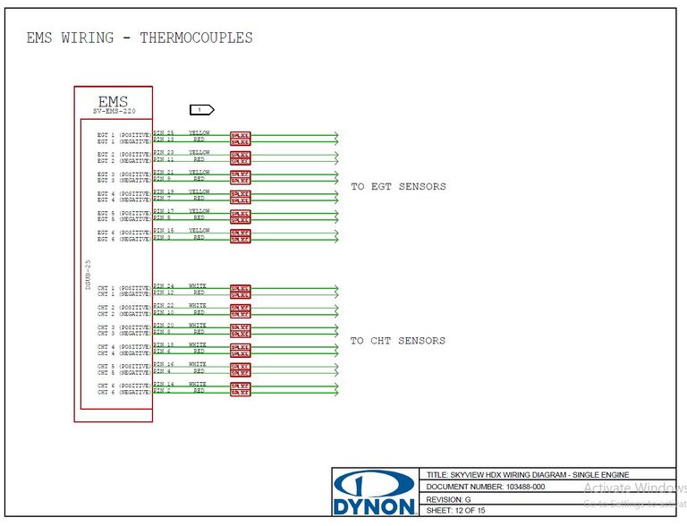
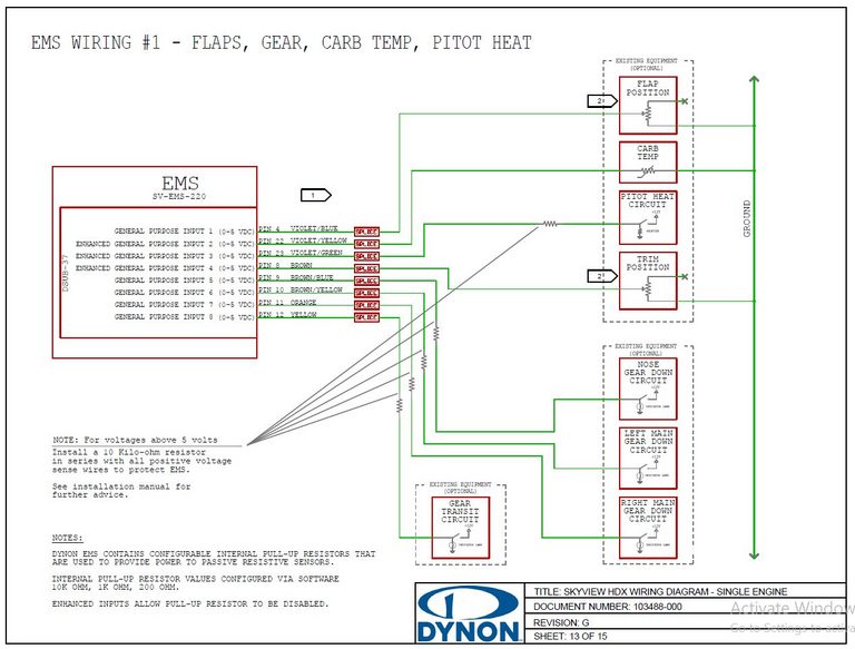
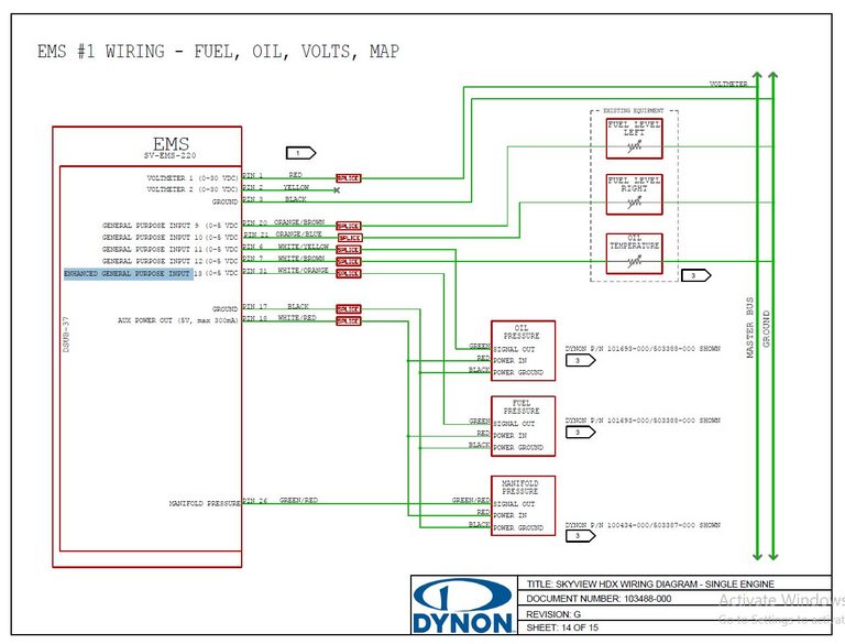
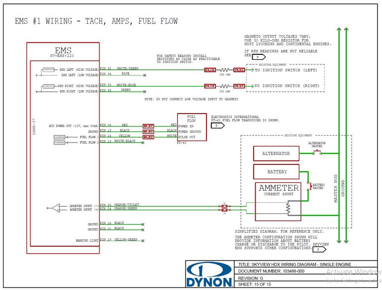
Extract of SKYVIEW HDX WIRING DIAGRAM - SINGLE ENGINE - Rev G
My assignments will be as follows:
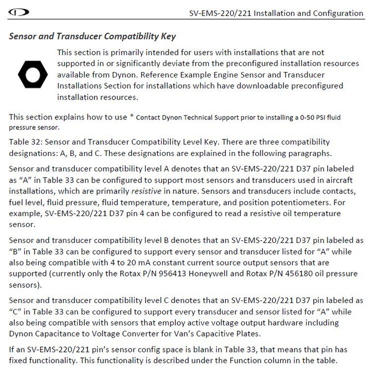
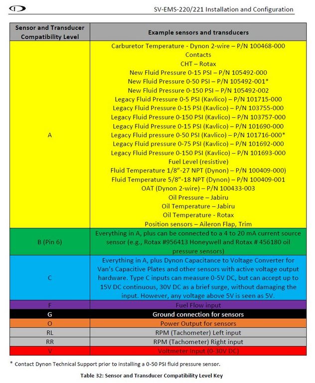
Enhanced general purpose inputs - configured for no-pullup resistors
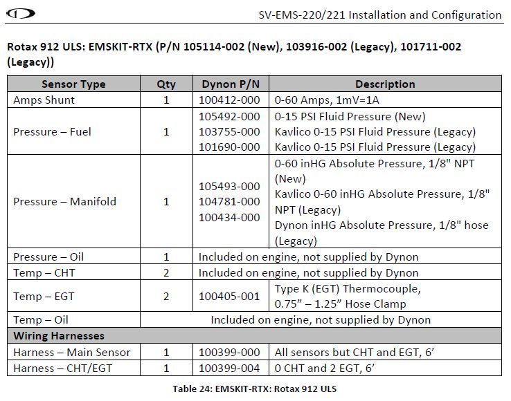
- Aithre EX2.0 powered from +5V auxillary output
- Flap potentiometer (3-wire connection between +5V auxillary output and gnd)
- Trim potentiometer (3-wire connection between +5V auxillary output and gnd)
- Fuel pressure (Kavlico P4055-5020-2 15psig) powered from +5V auxillary output)
All 4 enhanced general purpose inputs are used up, pins 8, 22, 23, 31
The +5V auxillary output also powers the manifold pressure
The oil pressure (Rotax 456180) output goes to the current-source capable general purpose input pin 6. This is a 2 wire connection.
The +12V auxillary output powers the
- oil pressure transducer
- fuel flow counter
The manifold pressure (Kavlico P4055-30A 30psi) output goes to the purpose-intended pin 26
I will reallocate the 3-core oil pressure wire to replace the map sensor wire which I had cut too short
I will replace the oil pressure wire with actual surplus 2-core wire
The shield and GND wires are all tied together at the EMS220
There are 6 ground pins available, the allocation of 4 pins is
- shield
- combined sensor gnd
- tachometer gnd
- sender gnd
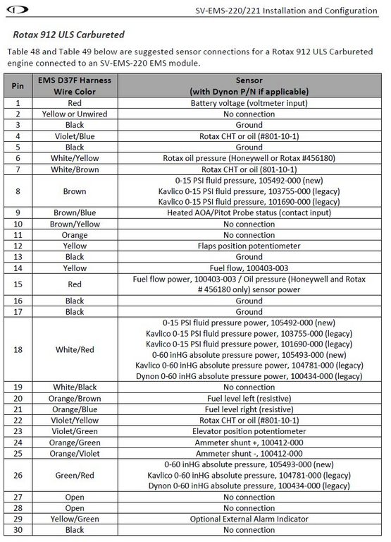
Actual EMS220 assignments in build
37 Pin Dsub connector
C37 P1 main bus voltage measure (this will be spliced into the backup battery input)
C37 P2 backup battery voltage measure
C37 P3 ground (EMS gnd ref - connected to gnd busbar via interconnect)
C37 P4 IBBS input low voltage detect
C37 P5 ground (aft sensor ground)
C37 P6 oil pressure
C37 P7 oil temperature
C37 P8 fuel pressure
C37 P9 charge system fault
C37 P10 cylinder 2 coolant temp
C37 P11 cylinder 4 coolant temp
C37 P12 main battery fault
C37 P13 ground (forward sensor ground)
C37 P14 fuel flow
C37 P15 auxillary +12V
C37 P16 ground (sensor shield)
C37 P17 ground (sender ground)
C37 P18 auxillary +5V
C37 P20 left fuel sender
C37 P21 right fuel sender
C37 P22 flap position
C37 P23 trim position
C37 P24/25 current shunt - P24 is +ve so goes to the red wire in the loom, P25 is -ve so goes to the blue wire in the loom, positive amps represents battery charge while negative amps corresponds to battery discharge
C37 P26 map sensor
C30 P30 ground (tachometer ground)
C37 P31 CO sensor
C37 P32/34 tachometer - connect one tachometer wire to pin 32, the other wire to ground
Ground pin usage (6 available) - 2 remains available
- sensors
- tachometer
- shield
- senders
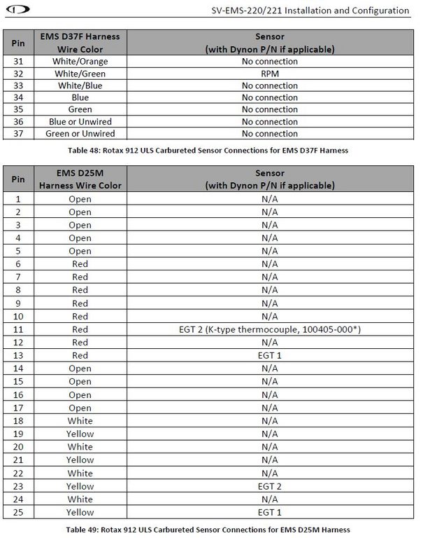
25 Pin Dsub connector
The SK-BM810 Type K thermistors have non-standard coloured leads, one black, one white
The black lead is slightly attracted to a powerful magnet, so it is the negative lead
From AI
In a Type K thermocouple, the negative leg (Alumel) is magnetic, while the positive leg (Chromel) is non-magnetic.
This magnetic property allows for polarity testing by applying a magnet to the wires; the wire that attracts the magnet more strongly is the negative terminal.
- Negative Wire: Alumel (Red in US standards) – Magnetic
- Positive Wire: Chromel (Yellow in US standards) – Non-magnetic
This magnetic characteristic is specific to Type K thermocouples and does not apply to Type S or other noble metal thermocouples.
Pins 19, 21, 23, 25 are positive so go to the white thermistor leads and multicoloured tefzel wires in the loom
Pins 7, 9, 11, 13 are negative so go to the black thermistor leads and associated black tefzel wires in the loom
C25 P19 EGT 4 green lead in loom
C25 P7 EGT 4 associated black lead
C25 P21 EGT 3 orange lead in loom
C25 P9 EGT 3 associated black lead
C25 P23 EGT 2 blue lead in loom
C25 P11 EGT 2 associated black lead
C25 P25 EGT1 white lead in loom
C25 P13 EGT1 associated black lead
This line is routed to the midsection interconnect
19 Apr 2026
C37 P4 backup battery low voltage warning dumped - the main bus voltage is monitored anyway. This is replaced by the pitot heat active signal
21 Apr 2026
The change above has been reverted
30 Apr 2026
Review of daisy-chained gnd, aux +5V and aux +12V circuits
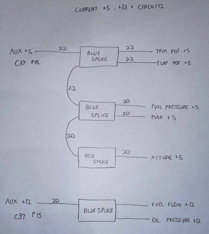
Current auxillary +5V and +12V circuits
Current gnd circuit
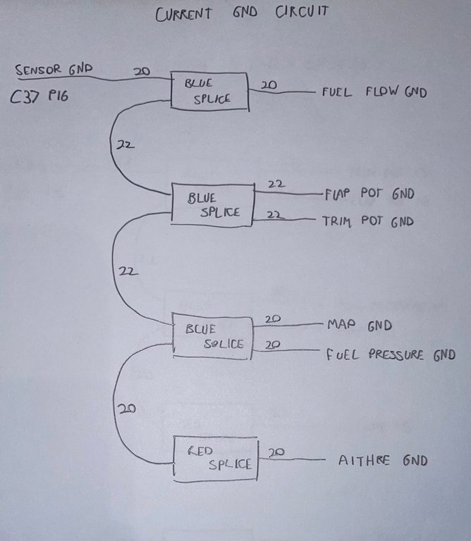
I wish to break this daisy chain up a little, to make the system more resilient to failure. There are two spare gnd pins on the D25 connector. Given
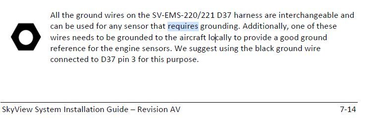
I need to run a separate GND wire from C37 pin 3 all the way to the ground busbar via the interconnect. There is one spare pin available on the connector A.
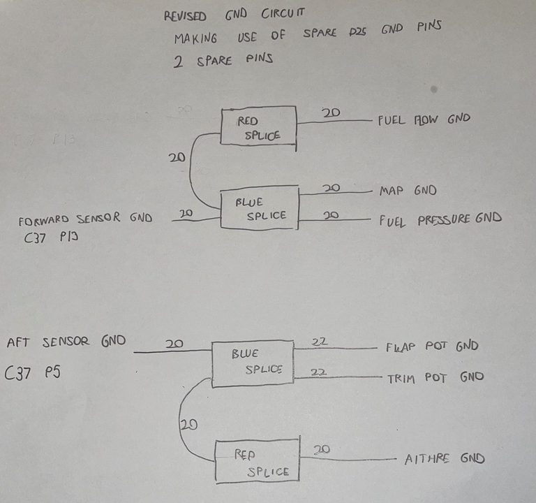
This leaves one spare pin on the 37-way connector, P5. I will split the gnd daisy-chain into two parts, one for firewall-forward sensors, and one for firewall-aft sensors. The table above is updated. The revised gnd wiring pattern is shown
Author
This post is from Adam Dickson
Progressive switch interior lighting circuit