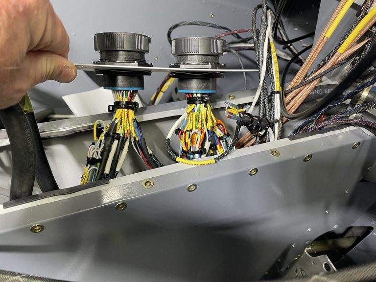
Midsection interconnect - panel connectors
There are two HDP24-24-47PE receptacles, panel mounting
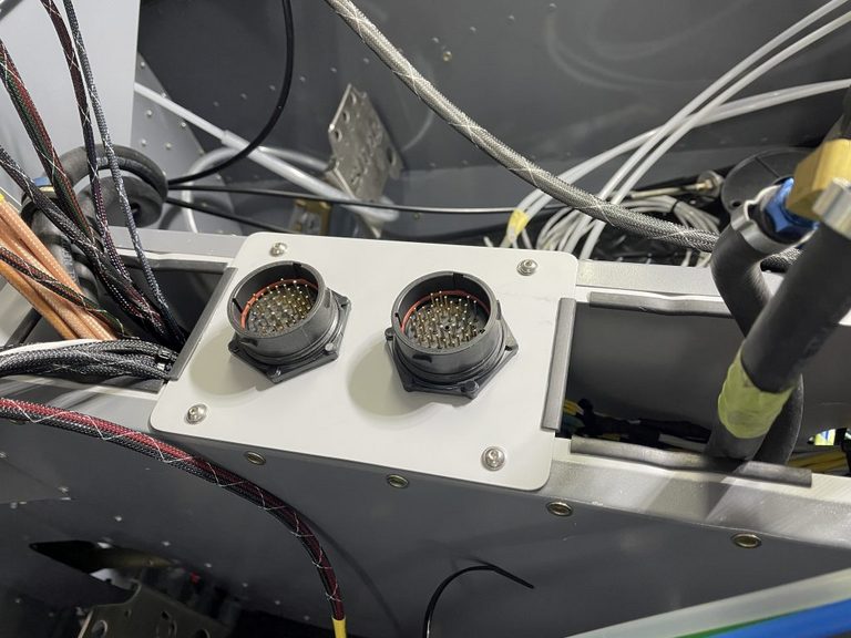 but with a mix of size 20
- 0460-202-2031 gold-plated for 20AWG and smaller
- 0460-010-20141 purple band nickel plated for 16-18AWG
and size 16 pins
- 0460-202-16141 nickel plated for 16AWG
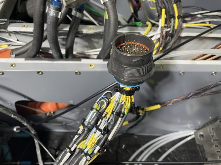
The front receptacle is designated A, the rear one is designated B. These are wired as per
https://webuildplanes.com/adam-dickson-sling2/p/6939/hdp20-pin-assignments-finalisation
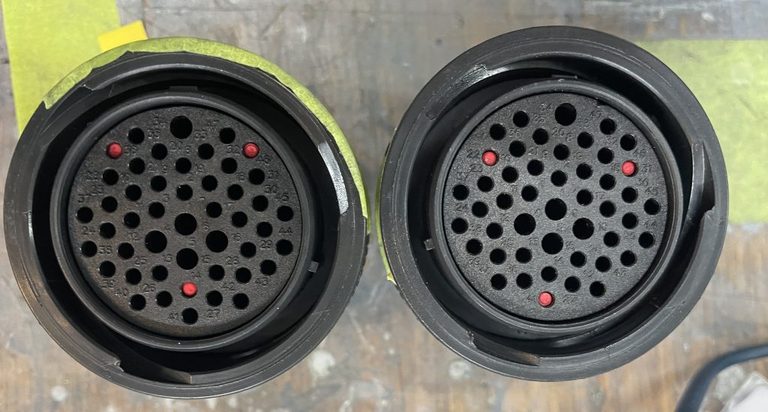
The HDP26-24-47SE plugs, shown below, have 0413-216-2005 keying pins to prevent them from being inserted into the incorrect receptacle
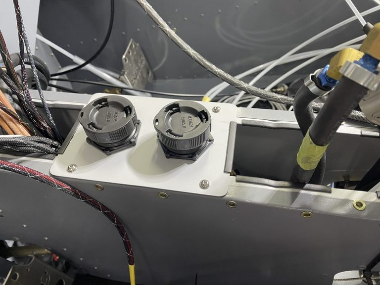
Protective covers HDC26-24 prevent foreign objects from falling in amongst the pins during servicing
In fact, with either connector removed all of its pins are dead, with a few exceptions. The only exceptions are on connector A where three pins are potentially live. These pins are as follows:
- The master contactor coil low side. This will be at the main battery potential, and is pulled to ground to close the master contactor. The current flow when pulled to ground is about 0.7A
- The backup battery master. This will be floating up near the backup battery potential, and is pulled to ground to activate the backup battery output
- The backup battery output. This pin will be live only when the backup battery master is pulled to ground, and is protected by a 10A blade fuse in the IBBS unit in the event of being live and also shorted to ground. The backup battery output is also live if the backup master is not pulled down but the main bus is live. The 10A fuse provides protection in the event of an unintended short to ground.
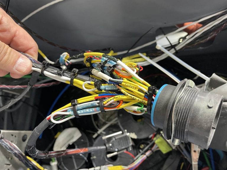
The underside view
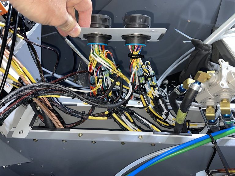
where I have individually labeled each wire and wire group, as per the link above. I have used cable ties to hold the bundles together temporarily with the intention replacing these with TESA 51036 tape.
Prior to assembly
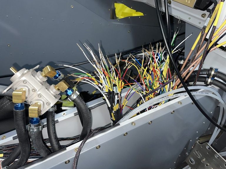
Much consolidation of wires are done at this location, to minimise the unnecessary use of interconnect pins. This consolidation is done with Sumitomo and Raychem butt-splices, which seal onto the wire insulation for added stability. The splices used are H-CR-436-36, H-CR-436-37, and H-CR-436-38 and their Raychem equivalents in a few cases
Author
Progressive switch interior lighting circuit
This post is from Adam Dickson