Aggregate shield wires in midsection interconnect
As mentioned in
https://webuildplanes.com/adam-dickson-sling2/p/6939/hdp20-pin-assignments-finalisation
in the section of May 23 the decision was taken to decouple the shield lines from the negative lines (which had been done earlier) at the midsection interconnect and instead aggregate all the shields together and pass these through a single pin. I am running out of pins on the midsection interconnects and this measure seems the best approach as the shields are all tied to precisely the same potential.
Summary:
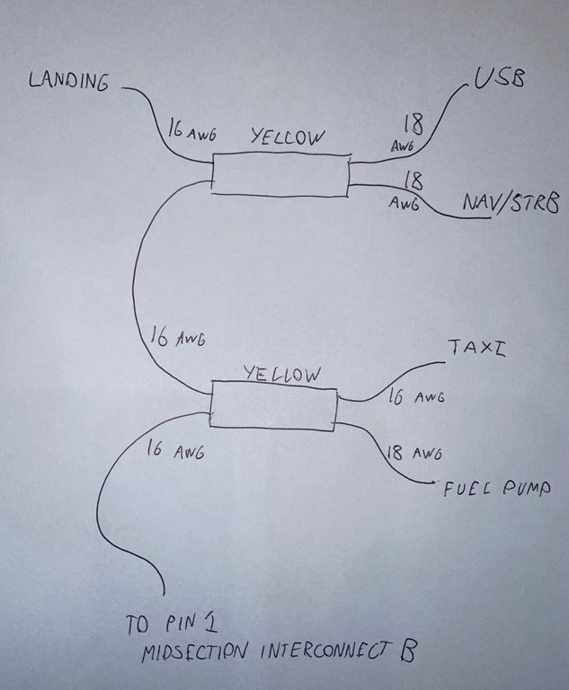
Midsection connector A - taxi lights and fuel pump shields are sub-aggregated
Midsection connector B - landing light, nav/strobe lights, USB are sub-aggregated
The ELT beacon ground and shield are left connected together and are not included in the aggregation
The ignition grounding arrangements are left unchanged
These sub-aggregations are then aggregated and passed to pin1 (size 16) on the midsection connector B
The choice of wire gauges in this aggregation are chosen to match the ratings of the power wires - so in the event of a single positive line to shield fault, the shield aggregation wiring is fully protected against excessive current by the circuit breakers in the respective positive supply path. The power circuits are protected by 10A and 7.5A circuit breakers. The size 16 pin is rated to 13A. It is therefore appropriate to connect this single connection on the midsection interconnect directly to the ground busbar
If protection of the shield aggregation wiring against multiple faults is desired it is necessary to install a circuit breaker in the connection of the aggregated shield to the ground busbar. This circuit breaker should not exceed 13A, but given that any current flow on the shield represents a fault it is appropriate to use a much lower rated breaker.
The problem is what to call this breaker, assuming it can even be fit on the panel. I am thinking of calling it "shields" with all the Star-Trek implications that would follow.
The wiring is diagrammed below:
Author
HDP20 pin assignments - finalisation
This post is from Adam Dickson