Finalise arrangement of CBs in compromise arrangement
From
the current arrangement of breakers is
Top row: 5, 5, 10, 10, 5, 5, 5, 5, 1, 1
Bottom row: 10, 3, 5, 5, 7.5, 10, 3, 2, 3, 1
The finalised list of main bus breakers in the main grouping is
- BK CHG - IBBS charge input 5A
- REG - regulator 1A
- TAXI LT - taxi lights 10A
- LDG LT - landing lights 10A
- AP - autopilot servos 5A
- NAV LT - navigation lights 5A
- STROBE - strobe lights 5A
- FLAPS - flaps 5A
- TRIM - trim 2A
- BOOST - boost pump 3A
- CAB LT - cabin light 1A
- BK BUS - (renamed from ESS BUS) essential bus breaker 10A
- START - start solenoid 5A
with the USB CB (7.5A) is now moved to the far right of the panel,
The finalised list of essential bus breakers is
- EFIS - main EFIS 5A
The revised and now finalised list of breakers on the avionics bus is
- COM - com radio 5A
- IC - intercom 1A
- XPNDR - transponder/ads-b in 3A
- BK EFIS - backup efis 1A
- FLARM- flarm 3A
- HDST -headset 1A
Now as to the arrangement, hopefully minimizing the number of CBs that need to be moved. A constraint is that the BOOST breaker must be at the far left of the array, preferably at the top
Lets have the avionics CBS located in the rightmost three positions top and bottom
Top row right 3
- orig: 5, 1, 1
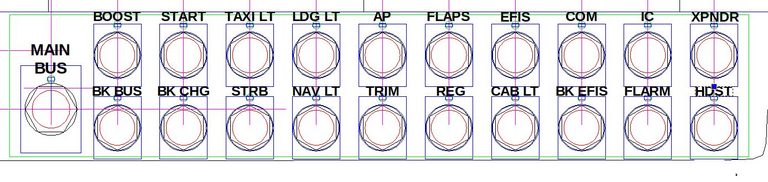
- revised: COM, IC, XPNDR 5,1,3
- a 5A breaker replaced with a 3A (from the main bus bottom row)
Bottom row right 3
- orig: 2, 3, 1
- revised: BK EFIS, FLARM, HDST 1, 3, 1
- a 2A breaker replaced with a 1A
Lets have the main and essential bus breakers on the left hand side, top and bottom rows
Top row left 6
- orig: 5, 5, 10, 10, 5, 5, 5
- revised: BOOST, START, TAXI LT, LDG LT, AP, FLAPS, EFIS 5,5,10,10, 5, 5, 5
The leftmost 5 positions will be on a 12.5mm busbar, the EFIS CB will be separately wired
Bottom row 6
- orig: 10, 3, 5, 5, 7.5, 10, 3
- revised: BK BUS, BK CHG, STRB, NAV LT, TRIM, REG, CAB LT 10, 5, 5, 5, 2, 1, 1
- a 3A breaker replaced with a 5A (from the avionics bus bottom row)
- a 7.5A breaker (removed to the far right of the panel) with a 2A (from the avionics bus bottom row)
- a 10A breaker (removed and set aside) replaced with a 1A (newly purchased)
- a 3 A breaker replaced with a 1A (newly purchased)
All six positions will be on a 10mm busbar
A total of 6 CBs need to be relocated, two new 1A breakers need to be purchased
Revised layout
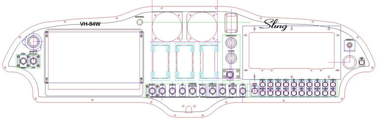
Overall panel
Author

This post is from Adam Dickson
Amendment of CB changes