Diagnosis of flap potentiometer problem
Following on from
So from the photos below, the associations on the potentiometer cable are as follows:
white with blue stripe labelled "BLU" connects to blue transmotec wire
white with orange stripe labelled "YEL" connects to yellow transmotec wire
white wire labelled "WHT" connects to white transmotec wire
red wire connects to red transmotec wire
green wire connects to black transmotec wire
The actuator is the trasmotec DLA-12-20-A-100-POT-IP65
https://transmotec.com/download/datasheets/transmotec-datasheet-dla-pot.pdf
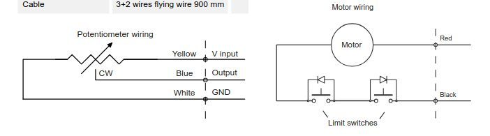
So the potentiometer wire is currently wired as follows:
GND is white wire labelled "WHT"
wiper is white with blue stripe labelled "BLU"
V input +5V is white with orange stripe labelled "YEL"
From
https://webuildplanes.com/adam-dickson-sling2/p/6916/ems220-pin-assignments
we have
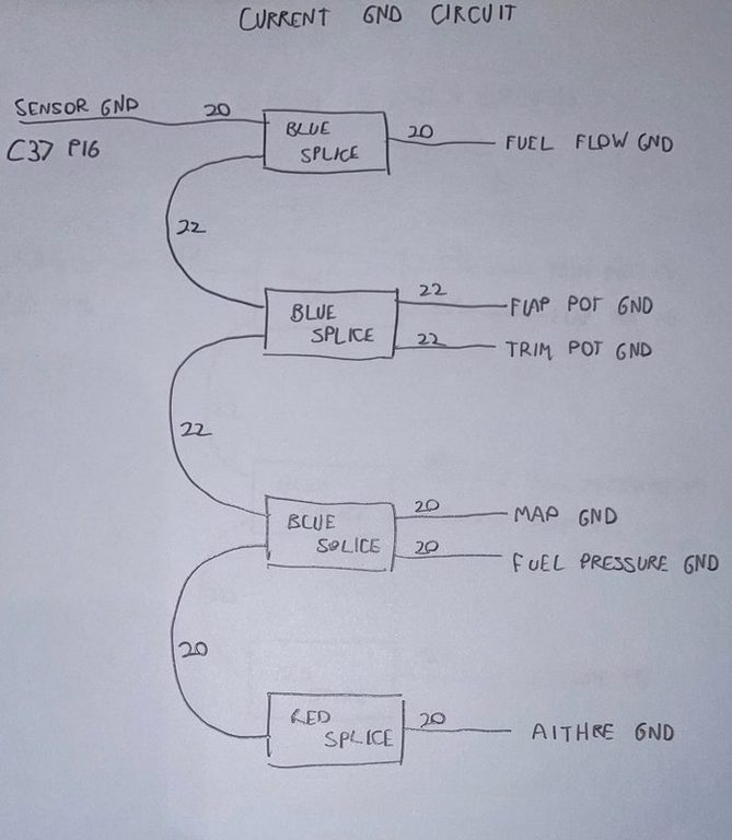
So the relevant ground is P16 of the 37 way connector
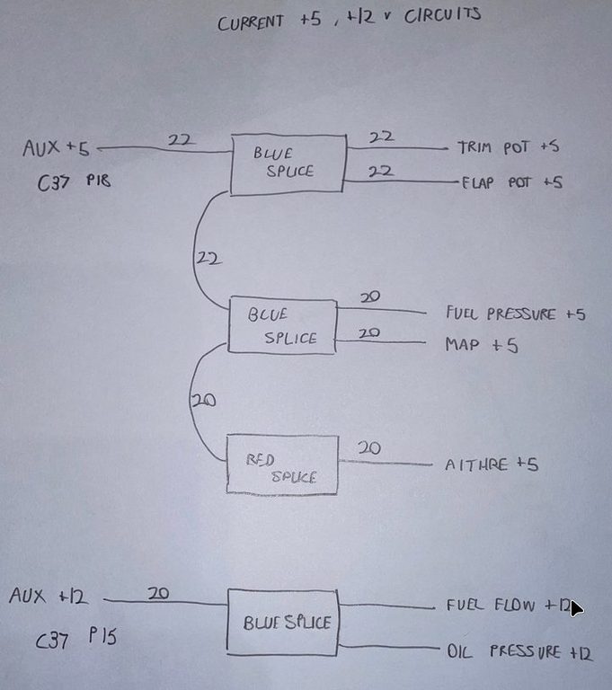
and the relevant AUX +5 circuit is P18 of the 37 way connector
Finally from the above document
C37 P5 ground (aft sensor ground)
C37 P16 ground (sensor shield)
C37 P18 auxillary +5V
C37 P22 flap position
We just need to confirm the above mapping by buzzing out
P5 (aft sensor ground) goes to BLU (wiper of potentiometer) - incorrect
P16 (sensor shield) goes to SHLD - correct
P18 (+5 AUX output) goes to YEL (Vinput of potentiometer) - corrent
P22 (flap position input) goes to WHT (GND of potentiometer) incorrect
Ok two wires in the flaps interconnect need to be transposed, namely the BLU and the WHT. The receptacle (with male pins) attached to the transmotec is the easiest to handle in this respect - the actual blue and white wires need to be swapped. But then for consistency the labels on the less accessible plug (with female sockets) also need to be swapped, so the revised association is
Fortunately
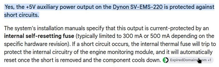
since at one flap extreme the +5 AUX output will have been shorted to ground
I will swap the labels at a later time, when the centre console barriers are disassembled. So the revised arrangement is bow
So from the photos below, the associations on the potentiometer cable are as follows:
white with blue stripe (revised) labelled "BLU" connects to white transmotec wire -> P5 aft sensor gnd connects to GND of potentiometer
white with orange stripe labelled "YEL" connects to yellow transmotec wire -> P18 +5 AUX connects to V input of potentiometer
white wire (revised) labelled "WHT" connects to blue transmotec wire -> P22 flap position input connects to wiper of potentiometer
red wire connects to red transmotec wire
green wire connects to black transmotec wire
This now operates correctly, with the flap position input configured as no-pulldown
Author

This post is from Adam Dickson